Shaft Design
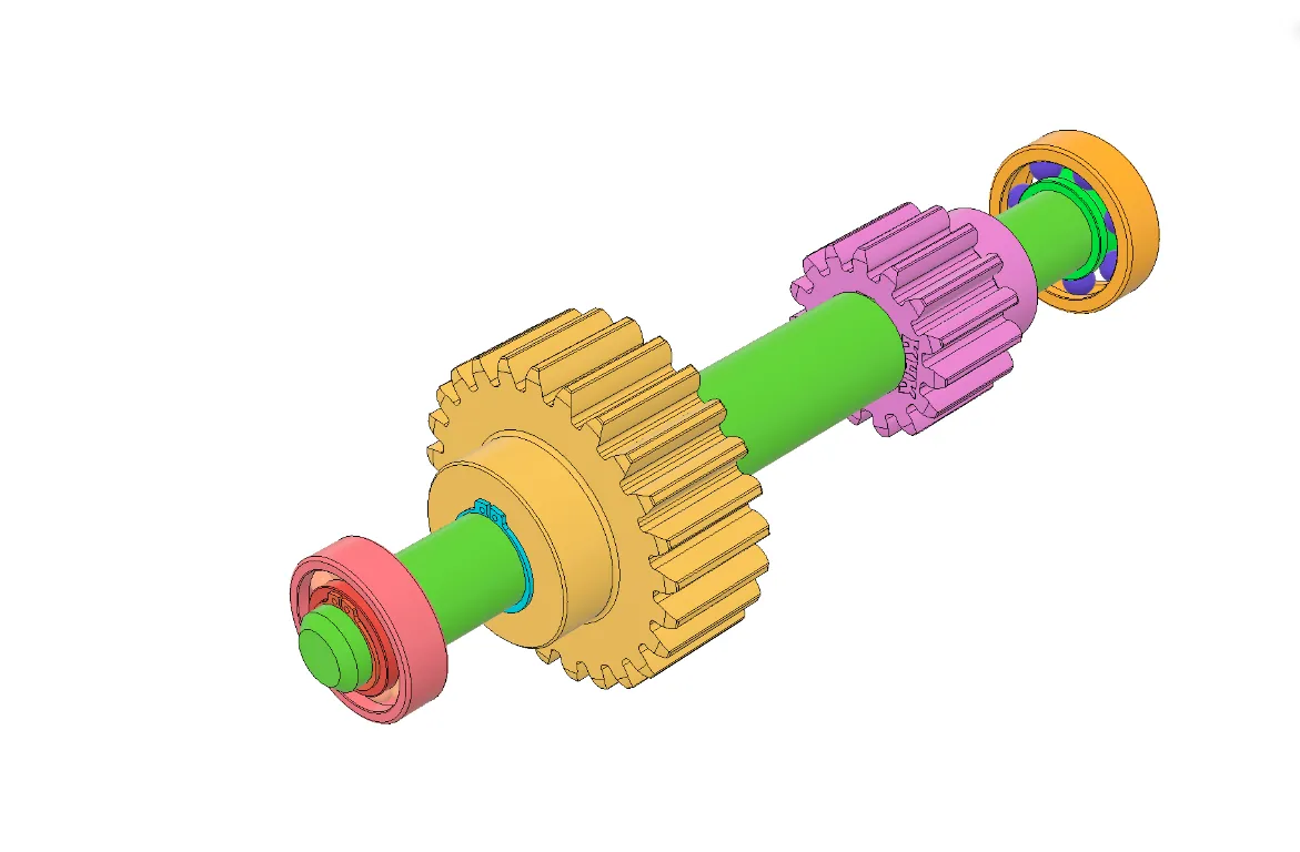
A shaft assembly design with two gears and bearing supports.
- Role
- Mechanical design
- Year
- 2026
- Status
- Complete
- Rev
- A
3D model
Loading 3D model…
More views
CAD views used to check the shaft, gears, and bearing supports as a complete assembly.
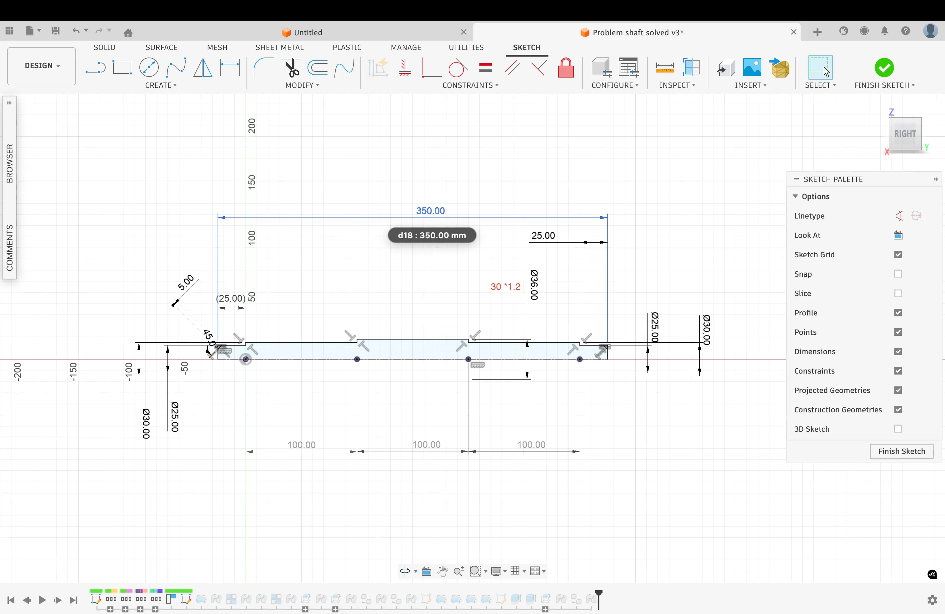
Dimensioned sketches and feature details used to define the stepped shaft and keyway.
McMaster-Carr retaining-ring specifications, the project parts list, and a gear sizing reference.
Overview
I designed a stepped shaft assembly carrying two gears, bearing supports, retaining rings, and machine keys. The work moved from a dimensioned shaft profile and feature sketches to a complete Fusion 360 assembly. Section and orthographic views helped me inspect how the components sit on the shaft, while catalog references informed the key and retaining-ring details.
Shaft design and fit
The shaft profile documents a 350 mm overall length with stepped Ø25 mm, Ø30 mm, and Ø36 mm sections. I laid out the keyway features in sketches and used the metric gear reference included in the project notes to position them relative to the gears.
I checked standard components against their published dimensions rather than treating the CAD geometry as arbitrary. The parts list records two 50 mm long, 8 mm wide machine keys, along with external retaining rings for 25 mm and 30 mm shaft sections. The McMaster-Carr references specify groove diameters of 23.9 mm and 28.6 mm, with corresponding groove widths of 1.3 mm and 1.6 mm. Those dimensions connect the purchased ring sizes to the retaining features modeled on the shaft.
Assembly checks
I brought the shaft, gears, bearings, keys, and retaining rings together in Fusion 360, then used section and side views to review component placement along the shaft. The gallery documents the process from the first assembly views and shaft sketches through the finished arrangement and catalog checks.