Shaft Housing
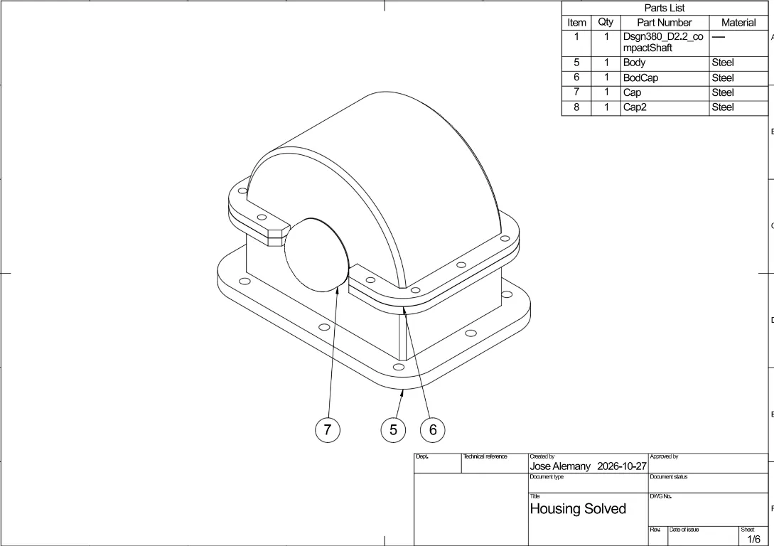
A mechanical design for a housing assembly built around a shaft, with a mounting base and detailed assembly drawing.
- Role
- Mechanical design
- Year
- 2026
- Status
- Complete
- Rev
- A
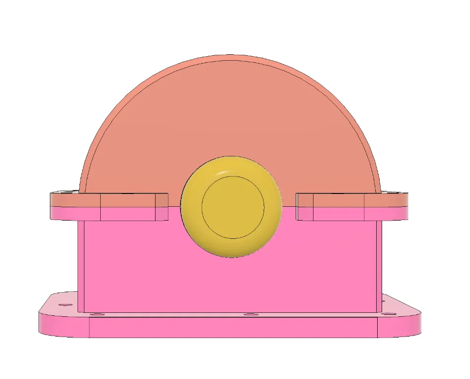
3D model
Loading 3D model…
More views
Fusion 360 views documenting the assembled housing, its mounting features, and the drawing views used to communicate the design.
Section analyses showing how the shaft, gears, bearings, and housing features align inside the enclosure.
Individual housing geometry and the dimensioned sketch used to lay out the enclosure and shaft opening.
Overview
I designed a split housing for a geared shaft assembly in Fusion 360. The enclosure combines a structural body, a removable upper cover, end caps around the shaft openings, and a mounting base. I developed the housing around the shaft and bearing arrangement, then used section analyses and orthographic views to check the internal clearances and component alignment.
Housing design
I modeled the housing components from scratch rather than adapting a catalog enclosure. The base flange provides the mounting footprint, while the split upper section allows access to the shaft and gears for assembly. The end-cap geometry supports the shaft openings, and the cover fastener pattern joins the upper housing to the body.
Bearing seats and assembly checks
I selected the bearings and retaining components from McMaster-Carr catalog parts, using their published dimensions to size the seats and related features. I considered the fit at each bearing seat so the bearings would locate securely without over-constraining the assembly.
The section views document the shaft, gears, and bearing supports inside the housing. I used these checks alongside the exterior and dimensioned views to review the cover split, shaft openings, mounting flange, and component clearances before completing the assembly drawing.