Stirling Engine
A small-scale Stirling engine built from a detailed manufacturing drawing package, with a focus on fabrication, alignment, and assembly accuracy.
- Role
- Assembly and fabrication
- Year
- 2025
- Status
- Complete
- Context
- MNFG 290 - Manufacturing Processes
- Rev
- B
3D model
Loading 3D model…
Loading…
Key numbers
- Top speed
- About 250 RPM
- Designed flywheel mass
- 115.98 g
- Designed flywheel inertia
- 3.016 × 10⁻⁴ kg·m²
- Mass removed from blank
- 64%
Overview
This project was a full small-scale Stirling engine build based on a manufacturing drawing booklet, with drawings by Chris Taggart at SAIT. The parts were designed in SolidWorks as a team. I did the entire assembly myself, and the build was individual: I built my engine from the same booklet on lathes, mills, and CNC equipment.
From drawings to parts
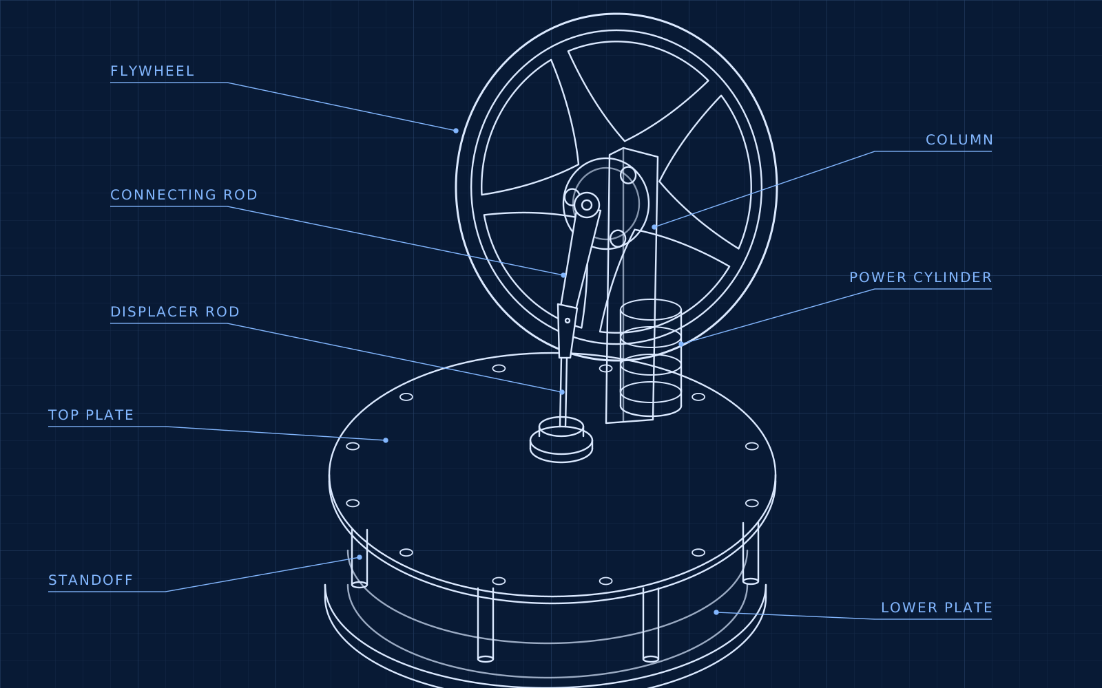
The engine was developed around a clear manufacturing plan: machine the required parts from raw stock, align the rotating components accurately, and assemble the power cylinder, displacer system, and flywheel in the correct sequence. The design package identified the major components, including the hot side plate, cold side plate, displacer cylinder, power cylinder, shaft, balancing components, and flywheel hub.
The project used a mix of fabricated and purchased parts. Key materials included aluminum for the plates and support structure, brass for the power cylinder and piston-related parts, mild steel for connecting rods, and drill rod for the shaft and pins. The shop procedures then guided the manufacturing steps: cutting, drilling, tapping, countersinking, turning, polishing, and final assembly.
Flywheel design
The flywheel was the one part each team member designed individually. Everyone started from the same blank: a 130 mm AISI 1020 cold-rolled steel plate, 3.18 mm thick and 324.29 g, with a fixed center hole and mounting pattern. The brief was to balance weight, cutting cost, and wasted material while still making an effective flywheel, so I had to consider the mass moment of inertia as well as the weight.
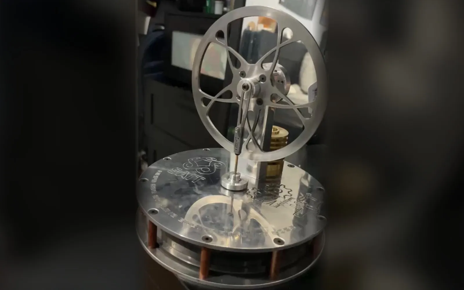
My design uses two rings and three spokes, which removes most of the blank but keeps material out at the larger radii. This is the wheel I studied and the one shown in the 3D model. It is not the wheel on the engine I built: to speed up laser cutting, everyone’s flywheel was cut from one preset design, which is the five-spoke wheel in the photo.
| Property | Value |
|---|---|
| Material | AISI 1020 steel, cold rolled |
| Final mass | 115.98 g |
| Mass removed from the blank | 208.31 g (64%) |
| Mass moment of inertia about the shaft | 3.016 × 10⁻⁴ kg·m² |
| Radius of gyration | 51 mm |
| Stored energy at 320 RPM | 0.17 J |
The mass and inertia of my design come from the SolidWorks mass properties saved in the part. The radius of gyration and stored energy are calculated from those values.
What I built
I assembled the complete model from the team’s parts on my own, then built the engine myself following the same drawings and processing instructions. The engine used a compact, mechanically simple layout with a flywheel-driven crank and link arrangement, and it was assembled around the central shaft and piston system.
The major fabricated elements were the hot and cold side plates, displacer cylinder, power cylinder, flywheel hub, bearing support, and balancing components. The work also included precise alignment checks and hand finishing to ensure the rotating assembly operated reliably and without excessive wobble.
Results
The final build followed a documented fabrication workflow and used the exact part structure laid out in the design package. The project emphasized practical manufacturing knowledge: getting the pieces to fit, confirming the tolerances, and understanding how each operation affected the final engine function.
The engine was designed at a 1:3 scale, with a 3 mm main shaft and a build that combined aluminum, brass, and steel components. The project’s value was not a large horsepower output; it was a successful demonstration of going from drawings to CAD to finished parts, and of hands-on assembly.
The finished engine, with the preset flywheel, reached a realistic maximum of about 250 RPM.
What I would change
If I continued this project, I would tighten the alignment and fit-up process around the shaft and piston assembly to reduce friction and improve run quality. I would also spend more time on finishing and balancing so the flywheel and rotating parts ran smoother under load.